I believe every boy who has a Matchbox® or Hot Wheels® car would love to know just how fast their car is going down hill.  In this case my son and I wanted to know this going down our stairs on the classic orange track.  After some research, I found a way using an Arduino Uno. This is a mega post so read on!
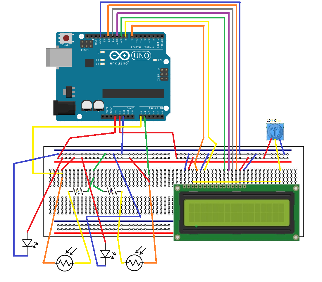
The setup is straight forward and the real help came from Mark’s post here.  Mark used a couple photo-resistors to setup a speed trap for his model trains.  Starting with Mark’s setup, I added a couple white LED’s and a 1602 LCD to provide data.  The LED’s make the photo-resistors more responsive and less susceptible to shadows when moving over the sensors.
The setup is straight forward with the diagram below.

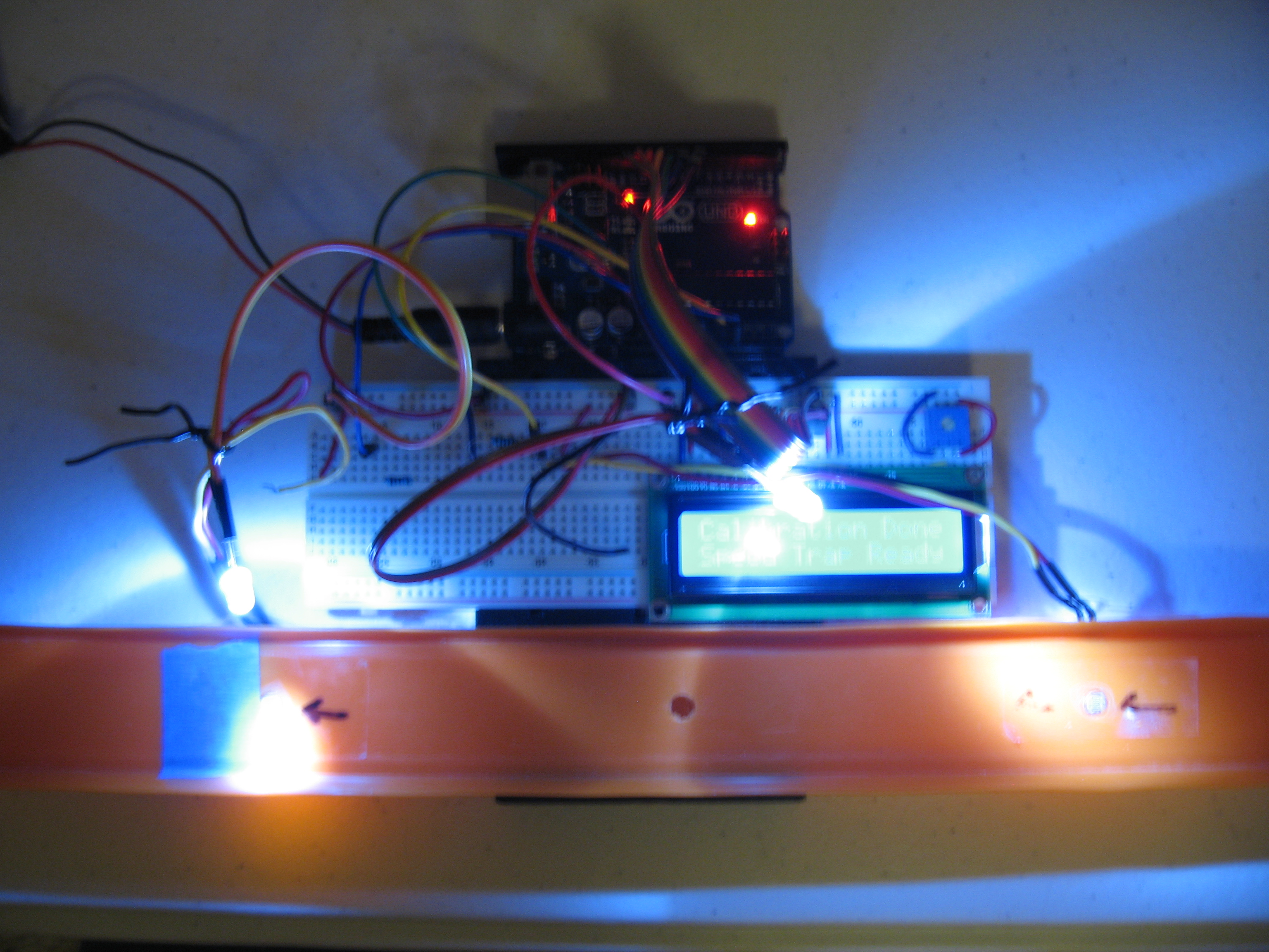
Here are a few photos of the setup:


The sketch / code for the Arduino is fairly easy (most of it is comments for others to understand and modify for future needs).
/**
 * Matchbox/Hot Wheels Speed Trap
 * Copyright (c) James Beam, 2015
 * This work is licensed under the Creative Commons
 * Attribution-NonCommercial-ShareAlike 3.0 Unported License.
 * To view a copy of this license, visit
 * http://creativecommons.org/licenses/by-nc-sa/3.0/.
 **/

/**A good bit of this code is modified from the original here:
 * http://englishjavadrinker.blogspot.com/2012/08/an-arduino-powered-scale-speed-trap.html
 * Many thanks to Mark's post!!
 * The additions include averages, counts, and adding a 1602 LCD, removing the red/green LEDs
 * Thanks also goto: http://playground.arduino.cc/Code/PrintFloats
 * This bit of code allows the serial port print outs to have more decimal points
 * The 1602 LCD allows use w/o a PC to see results and current average speed
**/

//keep the sketch size down by only compiling debug code into the
//binary when debugging is actually turned on
#define DEBUG 0

// set up the include for the the 1602 LCD
#include < LiquidCrystal.h >

// initialize the library with the numbers of the interface pins
LiquidCrystal lcd(7, 8, 9, 10, 11, 12);

// Set up float Print so the serial window will give more decimal places for car speed
// printFloat prints out the float 'value' rounded to 'places' places after the decimal point
// printFloat function originally found here: http://playground.arduino.cc/Code/PrintFloats
void printFloat(float value, int places) {
  // this is used to cast digits
  int digit;
  float tens = 0.1;
  int tenscount = 0;
  int i;
  float tempfloat = value;

  // make sure we round properly. this could use pow from , but doesn't seem worth the import
  // if this rounding step isn't here, the value  54.321 prints as 54.3209

  // calculate rounding term d:   0.5/pow(10,places)
  float d = 0.5;
  if (value < 0)
    d *= -1.0;
  // divide by ten for each decimal place
  for (i = 0; i < places; i++)
    d/= 10.0;
  // this small addition, combined with truncation will round our values properly
  tempfloat +=  d;

  // first get value tens to be the large power of ten less than value
  // tenscount isn't necessary but it would be useful if you wanted to know after this how many chars the number will take

  if (value < 0)
    tempfloat *= -1.0;
  while ((tens * 10.0) <= tempfloat) {
    tens *= 10.0;
    tenscount += 1;
  }

  // write out the negative if needed
  if (value < 0)
    Serial.print('-');

  if (tenscount == 0)
    Serial.print(0, DEC);

  for (i=0; i< tenscount; i++) {
    digit = (int) (tempfloat/tens);
    Serial.print(digit, DEC);
    tempfloat = tempfloat - ((float)digit * tens);
    tens /= 10.0;
  }

  // if no places after decimal, stop now and return
  if (places <= 0)
    return;

  // otherwise, write the point and continue on
  Serial.print('.');

  // now write out each decimal place by shifting digits one by one into the ones place and writing the truncated value
  for (i = 0; i < places; i++) {
    tempfloat *= 10.0;
    digit = (int) tempfloat;
    Serial.print(digit,DEC);
    // once written, subtract off that digit
    tempfloat = tempfloat - (float) digit;
  }
}

//all possible states of the state machine
const byte TRAP_CLEAR = 0;
const byte CAR_ENTER_TRAP = 1;
const byte CAR_LEAVING_TRAP = 2;

//the current state machine state
byte state = TRAP_CLEAR;

//the analog pins used for each sensor
const byte SENSOR_1 = 0;
const byte SENSOR_2 = 1;

//the threshold values for each sensor
int sensor1 = 1024;
int sensor2 = 1024;

//set the distance we are measuring in meters
const float distance = 0.20; // 0.20 m = 20 cm

//count the records, zeroize 1st
int count = 0;

//zero average speed variables
float speed_ave = 0;
float car_speed2 = 0;
float time_ave = 0;
float time_sum = 0;

//the time (in milliseconds) from the Arduino starting up that the
//first sensor was last triggered
unsigned long time;

//setup and calibrate the photo resistors
void setup(void) {

  //start the 1602 lcd
  lcd.begin(16, 2);

  //set up the serial port monitor
  //configure serial communication
  Serial.begin(9600);

  //let the user know we are calibrating the sensors
  Serial.print("Callibrating...");
  lcd.print("Callibrating...");

  //calibrate for 5 seconds (5000 ms)
  while (millis() < 5000) {
    //for the first five seconds check and store the lowest light
    //level seen on each sensor
    sensor1 = min(sensor1, analogRead(SENSOR_1));
    sensor2 = min(sensor2, analogRead(SENSOR_2));
  }

  //the cut off level for triggering the state machine
  //set at 0.25 the resistance seen during calibration
  sensor1 = sensor1*0.25;
  sensor2 = sensor2*0.25;

  //we have now finished callibration so tell the user...
  Serial.println(" Done, Speed Trap Ready");
  lcd.clear();
  lcd.print("Calibration Done");
  lcd.setCursor(0,1);  // set lcd to bottom row
  lcd.print("Speed Trap Ready");
}

//start scanning the timers
void loop(void) {

  if (state == TRAP_CLEAR) {
    //last time we checked the track was clear

    if (analogRead(SENSOR_1) < sensor1) {
      //but now the first sensor has been triggered so...

      //store the time at which the sensor was triggered
      time = millis();

      //advance into the next state
      state = CAR_ENTER_TRAP;

      //use for debug - prints when entry photo resistor is triggered
      //Serial.println("ENTER_TRAP");

    }
  }
  else if (state == CAR_ENTER_TRAP) {
    //the last time we checked the first sensor had triggered but
    //the second was yet to trigger

    if (analogRead(SENSOR_2) < sensor2) { //but now the second sensor has triggered as well so... //get the difference in ms between the two sensors triggering unsigned long diff = (millis() - time); // calculate real speed meters/second (m/s) float car_speed = float(distance*1000/diff); //count the records count++; //add up car speeds for average car_speed2 = car_speed + car_speed2; //add up times for average time_sum = diff + time_sum; if (count > 1){
        speed_ave = (float)car_speed2/count;
        time_ave = (float)time_sum/count;
      } else {
        speed_ave = car_speed;
        time_ave = diff;
      }

      //report the time and speed to the user
      Serial.print("Run: ");
      Serial.print(count);
      Serial.print(" , ");
      printFloat(car_speed,3);
      Serial.print(" m/s , ");
      Serial.print(diff);
      Serial.print(" ms , Ave Speed ");
      printFloat(speed_ave,3);
      Serial.print(" m/s , Ave Time ");
      Serial.println(time_ave);

      lcd.clear();  // clear the screen
      lcd.setCursor(0,0);  // set lcd to top row
      lcd.print(car_speed);
      lcd.print(" m/s ");
      lcd.print(diff);
      lcd.print(" ms");
      lcd.setCursor(0,1);  // set lcd to bottom row
      lcd.print("Run: ");
      lcd.print(count);
      lcd.print(" Av:");
      lcd.print(speed_ave);

      //set state car leaving the trap
      state = CAR_LEAVING_TRAP;

    }
  }
  else if (state = CAR_LEAVING_TRAP) {
    //last time we checked both sensors had triggered but both
    //had yet to reset back to normal
    if (analogRead(SENSOR_1) > sensor1 && analogRead(SENSOR_2) > sensor2) {
      //both sensors are now clear so...
      //move back to the first state ready for next time
      state = TRAP_CLEAR;

      //use for debug - prints when exit photo resistor is triggered
      //Serial.println("LEAVE_TRAP");
    }
  }
}
Once everything is loaded up and checked out, the LCD will report calibrating. This is the code recording the photo-resistors level with the LED’s, then the sensitivity is set to 25% of that level. This makes the photo-resistors react well when a car passes over them. Note the photo-resistors are spaced 20 cm (0.2 m) apart. During testing, they were initially 10 cm (0.1 m) apart. This worked well with slower cars; however, faster cars couldn’t be timed accurately. The larger space increases the time between the photo-resistors, and the accuracy.
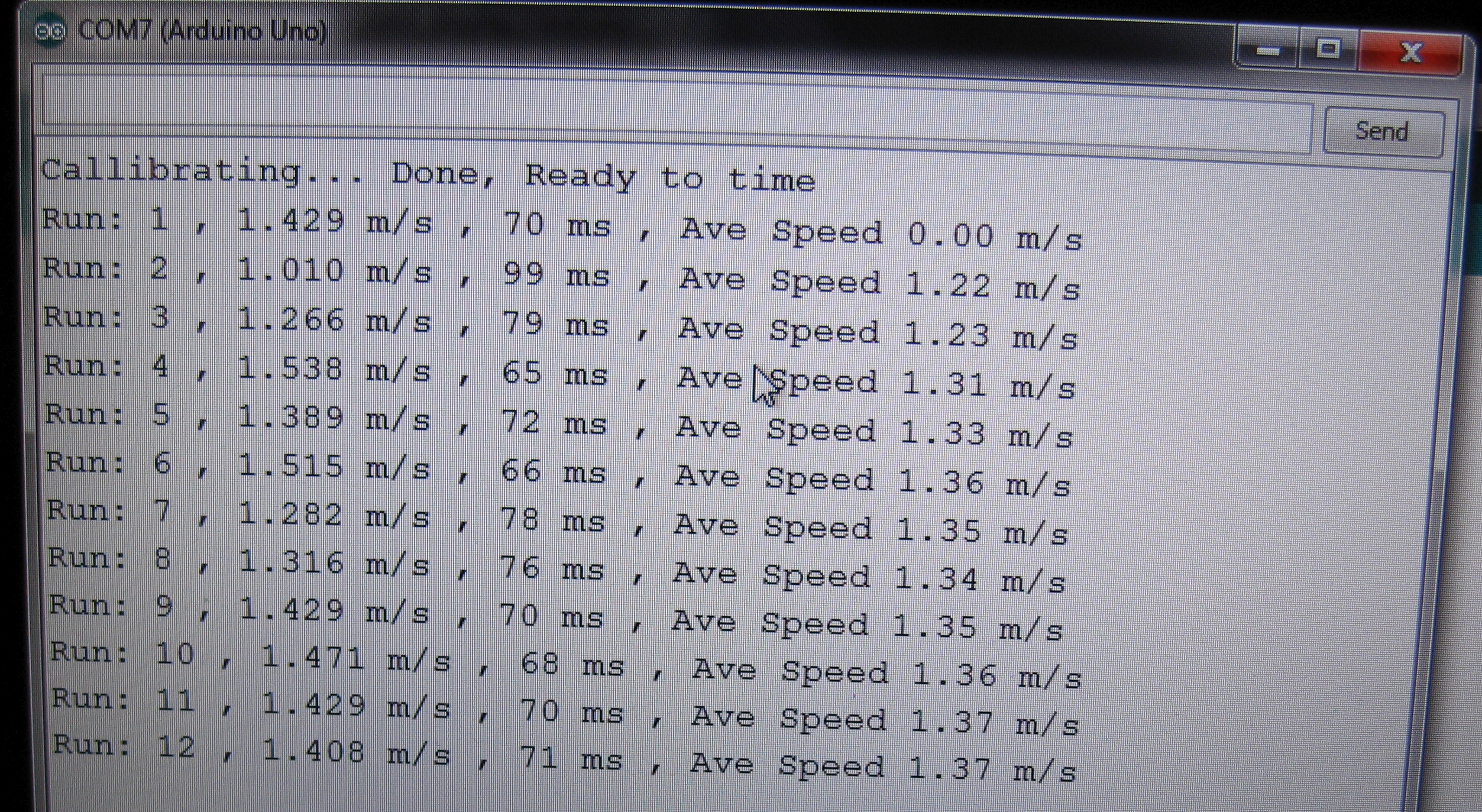
Once calibrated, running a car right to left (as seen in the pictures above) the LCD will report speed and the average speed. If you use the serial port monitor with the Arduino connected to a computer, the output will include average speed and trap times. Making it handy to repeat speed tests to reduce uncertainty and get better statistical data.

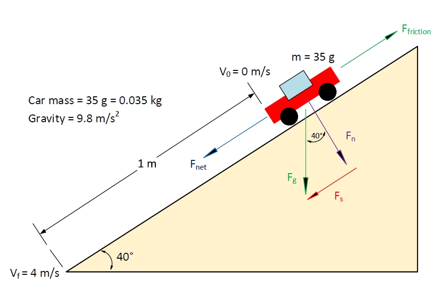
Car speed is just one part of the equation, the other part is using it practically. Â Using the diagram below we can figure out the forces and friction acting on the car with the physics & equations below.

In the test setup above, the 35 gram toy car from a stop, is measured to have a velocity of 4 m/s after rolling 1 m down the track at a 40° angle. To find the friction we need to determine all the forces shown above.
Fg is the force from gravity = 0.035 kg * 9.8 m/s = 0.343 N
Fn is the normal force from gravity = cos(40)*Fg = 0.766*0.343 N = 0.263 N
Fs is the force from gravity along the track = sin(40)*Fg = 0.643*0.343 N = 0.220 N
Ffriction is the friction force resisting the car from rolling down the track.
Fnet is the net force acting on the toy car, gravity force along the track minus friction forces resisting the car from rolling down the track, or
Fnet = Fs – Ffriction
To determine the friction forces, we need to determine Fnet.
Knowing the starting and final velocity, we can determine the toy car’s acceleration, and then using F = ma, find Fnet.
The car’s average velocity, Vave , is equal to ( Vf + V0 )/2 = ( 4 + 0 ) / 2 = 2 m/s
The time, T, for the car to roll down the track is the distance / Vave = 1 / 2 = 0.5 sec
The car’s acceleration, A, can be found using Vave = A * T
 ,
A = Vave / T = 2 / 0.5 = 4.0 m/s^2
Fnet can now be found using Fnet = m * A = 0.035 kg * 4.0 m/s^2 = 0.140Â N
Friction forces can now be found using Fnet = Fs – Ffriction , simplifying gives
Ffriction = Fs – Fnet = 0.220 N – 0.140 N = 0.080 N
Thus the friction forces acting on the toy car total 0.080 Newtons. The total friction forces include rolling friction as well as drag from moving through the air. Â These values depend on many factors like surface area, contact materials, and loading – we won’t go into that here.
So to conclude this massive post, we have a speed trap to get speed, and the physics to support finding additional data for testing and fun! Â The setup could also be modified to be on two tracks and with some code changes to see which car arrives first (think a drag race). Â If you have made it this far down, thanks and I hope you enjoyed the post!
Download link below is a ZIP file containing the sketch file, Visio file with diagram, images etc. (handy for other science projects and work). Â Teachers/Instructors/Students if you use this please let me know with an email (no legal stuff, would like to know if this is handy).
Click here to get the file.
File MD5 sum: B2A268447512001FCE00D1488D24DAE9
[NOTE: updated the diagram and download on 2016-01-31 with corrections for the 2 line display wiring]


