Use VLC Player to delay radio input to sync with Live TV (update)

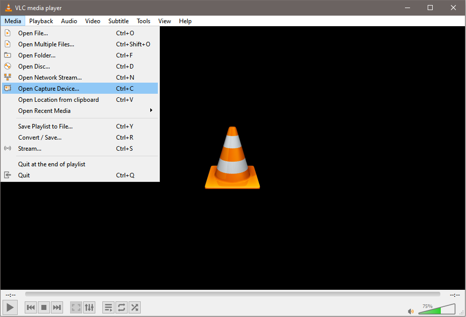
Are you faced with annoying Live Sports TV announcers?
Prefer to hear more experienced radio announcers?
There is a way to do this and not hear the radio play before the TV shows the play!

Tools/items needed:
1. Laptop with VLC Player
2. A pocket radio with stereo headphone output, 3.5 mm mini-DIN
3. A USB stereo audio adapter
4. An audio extension cable(s) – you may need another adapter depending on your playback device.

STEPS:
0. Mute your TV – you don’t want to hear those announcers anymore
1. Install VLC player on your laptop
2. Setup/tune your pocket radio to the station with the sports event.
3. Connect the USB stereo adapter to your laptop
4. Connect the audio extension cable from pocket radio output to the USB audio adapter MIC input.
5. Connect USB audio adapter headphone output to your playback device (this could be a stereo, a portable speaker, or other audio device), but DO NOT connect to your TV
6. Now on your laptop, open up VLC Player.
7. Select Open -> Capture Media Device (or CTRL-C in Windows)

8. Set “Capture Mode” to “Direct Show”
9. Set “Video Device Name” to “None”
10. Set “Audio Device Name” to “Microphone (2-C-Media USB Audio Device)”
11. Here is real import part, check the “Show more options” box
12. Set “Caching” to the desired time delay – 1000 ms = 1 second, so 15000 ms is 15 seconds. You’ll have to play around with this setting. Sometimes the delay is only around 11 seconds, sometimes it can be 25 seconds. Your settings should look like the image below.

13. Click the “Play” button. Now wait your delay time, as the radio input will cache (buffer up) the time, then play through the USB audio output.
14. Typically I need 4 to 5 trys to get the timing right, but after that it is set. For USA football, I like to use a stop watch to hear the anouncer call the snap until I see it on TV (for example).

Hope this works for you and happy listening!

Lenovo Y510P v3.05 BIOS Bricked Crisis Recovery [Solved]

Like most Lenovo™ Y510P© owners who want to use a faster speed wireless LAN card (that for some unknown reason Lenovo has black listed on the Y510P/Y410P BIOS) , I have updated my BIOS to a modified v3.05 version.

However, such unlocked BIOS’ have dangers in which an improper setting can result in the laptop not functioning (or worse damage to the motherboard).  In my case, I made a change to the built-in display settings and resulted in a headless non-functioning laptop. Of course this can be very disconcerting given the cost of a well equipped and modified laptop!

If you dig around you’ll find several methods and procedures all that are very conflicting.  So after a two near sleepless nights, I was able to recover my laptop!  While I can’t promise this will save yours, there is a way!   My Y510P was made late November 2013 and has an Nvidia GT-755 video (note some older Y510P’s have a 750).   What I’m getting at is to check your hardware and compare notes before following/using this, as your mileage may vary.  While unconfirmed, this process will likely recover a Y410P too.

The Recovery . . .
First you’ll need Lenovo’s stock v3.05 BIOS (this is critical) as the file load provided has both the default and crisis BIOS .BIN images needed to recover.  So here it is very important to know which BIOS you are using before starting, for this tutorial it must be v3.05! The download link above has the stock v3.05 ZIP file you’ll need.

Unzip the file and in the file structure you’ll find a folder called crisis†.  In this folder is the  “Yx01.bin” file you’ll need for the initial recovery.
Read all the below (twice) before starting!
1) Use a small 1G or 2G USB thumb drive (preferably with a working activity LED, see note 9 below) and format it as FAT only (can also try FAT32 but this is untested by me)
2) Copy only the “Yx01.bin” file to the drive – nothing else
3) Remove the battery from your Y510P
4) Remove the external power cable
5) Insert the thumb drive in the USB port next to the HDMI connector
6) Hold down the “Fn” and “R” at the same time (do not release until step 9) ‡
7) Insert the external power (still holding the  “Fn” and “R” buttons down)
8) Briefly press the power button
9) The laptop will try to start and will read the thumb drive, here is where the USB thumb drive activity LED comes in handy, when you see drive activity release the  “Fn” and “R” buttons
10) CRITICAL, DO NOT TOUCH ANYTHING ON THE LAPTOP OR REMOVE POWER!! At this point the fan will run at full speed, LED’s may or may not blink – the magic is happening here – you bricked BIOS is being re-written with the crisis BIOS (Yx01.BIN) file!
11) The laptop will power off briefly when done, and then restart.
12) With luck, you’ll now be able to access the BIOS screen via pressing F2 during boot up

Next Steps . . .
Now that your crisis recovery BIOS is back, you should re-flash it with the full stock v3.05.

Option 1:
Be sure the laptop battery is installed and fully charged and connected to external power & If you are running windows, run “VIQYx305.exe” from the Win Flash directory.

Option 2:
If you don’t have Windows or don’t trust Windows, use a thumb drive boot to Free DOS.  Be sure the laptop batter is installed and fully charged and connected to external power.
1) Creating a Free DOS boot disk, use your original thumb drive from the recovery.
2) Download Rufus, and make the thumb drive (see image below)
3) Make a directory called y510BIOS
4) Copy all the extracted files from the ZIP download to the y510BIOS directory
5) Boot the thumb drive by restarting and pressing the F5 button, select the thumb drive.
6) Boot will be fast and arrive at a DOS prompt
7) Change to the  y510BIOS direct by typing   cd y510BIOS
8) Now type  flash.bat  and press enter
9) The laptop will flash the BIOS and EC, BIOS will load first, EC second.  During the EC flash the fan will run full speed. When complete the laptop will reboot with the fully updated BIOS.
10) Enjoy the updated BIOS

Rufus Free DOS setup:

rufus_sc

Rufus Setup

Other helpful tools/sources:
Phoenix Tool  – this tool is handy to help identify the recovery BIOS file needed.  When ran using the BIOS “BIN” file, the tool will yield “Yx01.bi?” confirming that the “Yx01.bin” file is to be used for the crisis recovery.

† bios-mods.com has a great listing on how to recover the an Insyde BIOS (what the Y510P and Y410P use)
‡ This post at bios-mods.com was handy to find the working “Fn + R” key combination, several other posts on the web will point to the “Fn + B” combination; however, the the “Fn + B” combination didn’t work for my laptop (it may for yours), be ready to try all 12 combinations!

Final note: I wanted to post this on techinferno.com; but, with their recent user changes my approved user account “jmbneaf” was moved, lost, discarded (apparently you have to post there, like everyday, to keep a membership).  Nonetheless, my post is here on my blog & I  hope that this finds users well (including those from techinferno too) and helps other Y510P / Y410P users recover their accidentally bricked BIOS.

Matchbox® or Hot Wheels® car Speed Trap using an Arduino Uno

I believe every boy who has a Matchbox® or Hot Wheels® car would love to know just how fast their car is going down hill.  In this case my son and I wanted to know this going down our stairs on the classic orange track.  After some research, I found a way using an Arduino Uno. This is a mega post so read on!

The setup is straight forward and the real help came from Mark’s post here.  Mark used a couple photo-resistors to setup a speed trap for his model trains.  Starting with Mark’s setup, I added a couple white LED’s and a 1602 LCD to provide data.  The LED’s make the photo-resistors more responsive and less susceptible to shadows when moving over the sensors.

The setup is straight forward with the diagram below.

breadboard_layout

Here are a few photos of the setup:
IMG_3551 IMG_3553

The sketch / code for the Arduino is fairly easy (most of it is comments for others to understand and modify for future needs).

/**
 * Matchbox/Hot Wheels Speed Trap
 * Copyright (c) James Beam, 2015
 * This work is licensed under the Creative Commons
 * Attribution-NonCommercial-ShareAlike 3.0 Unported License.
 * To view a copy of this license, visit
 * http://creativecommons.org/licenses/by-nc-sa/3.0/. 
 **/

/**A good bit of this code is modified from the original here:
 * http://englishjavadrinker.blogspot.com/2012/08/an-arduino-powered-scale-speed-trap.html
 * Many thanks to Mark's post!! 
 * The additions include averages, counts, and adding a 1602 LCD, removing the red/green LEDs
 * Thanks also goto: http://playground.arduino.cc/Code/PrintFloats
 * This bit of code allows the serial port print outs to have more decimal points
 * The 1602 LCD allows use w/o a PC to see results and current average speed
**/ 
 
//keep the sketch size down by only compiling debug code into the
//binary when debugging is actually turned on
#define DEBUG 0

// set up the include for the the 1602 LCD
#include < LiquidCrystal.h >

// initialize the library with the numbers of the interface pins
LiquidCrystal lcd(7, 8, 9, 10, 11, 12);

// Set up float Print so the serial window will give more decimal places for car speed
// printFloat prints out the float 'value' rounded to 'places' places after the decimal point
// printFloat function originally found here: http://playground.arduino.cc/Code/PrintFloats
void printFloat(float value, int places) {
  // this is used to cast digits 
  int digit;
  float tens = 0.1;
  int tenscount = 0;
  int i;
  float tempfloat = value;

  // make sure we round properly. this could use pow from , but doesn't seem worth the import
  // if this rounding step isn't here, the value  54.321 prints as 54.3209

  // calculate rounding term d:   0.5/pow(10,places)  
  float d = 0.5;
  if (value < 0)
    d *= -1.0;
  // divide by ten for each decimal place
  for (i = 0; i < places; i++)
    d/= 10.0;    
  // this small addition, combined with truncation will round our values properly 
  tempfloat +=  d;

  // first get value tens to be the large power of ten less than value
  // tenscount isn't necessary but it would be useful if you wanted to know after this how many chars the number will take

  if (value < 0)
    tempfloat *= -1.0;
  while ((tens * 10.0) <= tempfloat) {
    tens *= 10.0;
    tenscount += 1;
  }

  // write out the negative if needed
  if (value < 0)
    Serial.print('-');

  if (tenscount == 0)
    Serial.print(0, DEC);

  for (i=0; i< tenscount; i++) {
    digit = (int) (tempfloat/tens);
    Serial.print(digit, DEC);
    tempfloat = tempfloat - ((float)digit * tens);
    tens /= 10.0;
  }

  // if no places after decimal, stop now and return
  if (places <= 0)
    return;

  // otherwise, write the point and continue on
  Serial.print('.');  

  // now write out each decimal place by shifting digits one by one into the ones place and writing the truncated value
  for (i = 0; i < places; i++) {
    tempfloat *= 10.0; 
    digit = (int) tempfloat;
    Serial.print(digit,DEC);  
    // once written, subtract off that digit
    tempfloat = tempfloat - (float) digit; 
  }
}
 
//all possible states of the state machine
const byte TRAP_CLEAR = 0;
const byte CAR_ENTER_TRAP = 1;
const byte CAR_LEAVING_TRAP = 2;
 
//the current state machine state
byte state = TRAP_CLEAR;
 
//the analog pins used for each sensor
const byte SENSOR_1 = 0;
const byte SENSOR_2 = 1;
 
//the threshold values for each sensor
int sensor1 = 1024;
int sensor2 = 1024;
 
//set the distance we are measuring in meters
const float distance = 0.20; // 0.20 m = 20 cm

//count the records, zeroize 1st
int count = 0;

//zero average speed variables 
float speed_ave = 0;
float car_speed2 = 0;
float time_ave = 0;
float time_sum = 0;

//the time (in milliseconds) from the Arduino starting up that the
//first sensor was last triggered
unsigned long time;

//setup and calibrate the photo resistors   
void setup(void) {   
  
  //start the 1602 lcd
  lcd.begin(16, 2);
  
  //set up the serial port monitor
  //configure serial communication
  Serial.begin(9600);
     
  //let the user know we are calibrating the sensors
  Serial.print("Callibrating...");
  lcd.print("Callibrating...");

  //calibrate for 5 seconds (5000 ms) 
  while (millis() < 5000) {
    //for the first five seconds check and store the lowest light
    //level seen on each sensor
    sensor1 = min(sensor1, analogRead(SENSOR_1));
    sensor2 = min(sensor2, analogRead(SENSOR_2));
  }
   
  //the cut off level for triggering the state machine
  //set at 0.25 the resistance seen during calibration
  sensor1 = sensor1*0.25;
  sensor2 = sensor2*0.25;  
   
  //we have now finished callibration so tell the user...
  Serial.println(" Done, Speed Trap Ready");
  lcd.clear();
  lcd.print("Calibration Done");
  lcd.setCursor(0,1);  // set lcd to bottom row
  lcd.print("Speed Trap Ready");
}

//start scanning the timers 
void loop(void) {
     
  if (state == TRAP_CLEAR) {
    //last time we checked the track was clear
     
    if (analogRead(SENSOR_1) < sensor1) {
      //but now the first sensor has been triggered so...
       
      //store the time at which the sensor was triggered
      time = millis();
 
      //advance into the next state
      state = CAR_ENTER_TRAP;
      
      //use for debug - prints when entry photo resistor is triggered
      //Serial.println("ENTER_TRAP");
 
    }
  }
  else if (state == CAR_ENTER_TRAP) {
    //the last time we checked the first sensor had triggered but
    //the second was yet to trigger
     
    if (analogRead(SENSOR_2) < sensor2) { //but now the second sensor has triggered as well so... //get the difference in ms between the two sensors triggering unsigned long diff = (millis() - time); // calculate real speed meters/second (m/s) float car_speed = float(distance*1000/diff); //count the records count++; //add up car speeds for average car_speed2 = car_speed + car_speed2; //add up times for average time_sum = diff + time_sum; if (count > 1){
        speed_ave = (float)car_speed2/count;
        time_ave = (float)time_sum/count;
      } else {
        speed_ave = car_speed;
        time_ave = diff; 
      }
      
      //report the time and speed to the user
      Serial.print("Run: ");
      Serial.print(count);
      Serial.print(" , ");
      printFloat(car_speed,3);
      Serial.print(" m/s , ");
      Serial.print(diff);
      Serial.print(" ms , Ave Speed ");
      printFloat(speed_ave,3);
      Serial.print(" m/s , Ave Time ");
      Serial.println(time_ave);
      
      lcd.clear();  // clear the screen
      lcd.setCursor(0,0);  // set lcd to top row
      lcd.print(car_speed); 
      lcd.print(" m/s ");
      lcd.print(diff);
      lcd.print(" ms");
      lcd.setCursor(0,1);  // set lcd to bottom row
      lcd.print("Run: ");
      lcd.print(count); 
      lcd.print(" Av:");
      lcd.print(speed_ave);

      //set state car leaving the trap
      state = CAR_LEAVING_TRAP;
      
    }
  }
  else if (state = CAR_LEAVING_TRAP) {
    //last time we checked both sensors had triggered but both
    //had yet to reset back to normal 
    if (analogRead(SENSOR_1) > sensor1 && analogRead(SENSOR_2) > sensor2) {
      //both sensors are now clear so...
      //move back to the first state ready for next time
      state = TRAP_CLEAR;
      
      //use for debug - prints when exit photo resistor is triggered
      //Serial.println("LEAVE_TRAP"); 
    }
  }
}

Once everything is loaded up and checked out, the LCD will report calibrating. This is the code recording the photo-resistors level with the LED’s, then the sensitivity is set to 25% of that level. This makes the photo-resistors react well when a car passes over them. Note the photo-resistors are spaced 20 cm (0.2 m) apart. During testing, they were initially 10 cm (0.1 m) apart. This worked well with slower cars; however, faster cars couldn’t be timed accurately. The larger space increases the time between the photo-resistors, and the accuracy.

Once calibrated, running a car right to left (as seen in the pictures above) the LCD will report speed and the average speed. If you use the serial port monitor with the Arduino connected to a computer, the output will include average speed and trap times. Making it handy to repeat speed tests to reduce uncertainty and get better statistical data.

serial_monitor_output

Car speed is just one part of the equation, the other part is using it practically.  Using the diagram below we can figure out the forces and friction acting on the car with the physics & equations below.

car_free_body_diagram


In the test setup above, the 35 gram toy car from a stop, is measured to have a velocity of 4 m/s after rolling 1 m down the track at a 40° angle. To find the friction we need to determine all the forces shown above.
Fg is the force from gravity = 0.035 kg * 9.8 m/s = 0.343 N
Fn is the normal force from gravity = cos(40)*Fg = 0.766*0.343 N = 0.263 N
Fs is the force from gravity along the track = sin(40)*Fg = 0.643*0.343 N = 0.220 N
Ffriction is the friction force resisting the car from rolling down the track.
Fnet is the net force acting on the toy car, gravity force along the track minus friction forces resisting the car from rolling down the track, or
Fnet = Fs – Ffriction

To determine the friction forces, we need to determine Fnet.
Knowing the starting and final velocity, we can determine the toy car’s acceleration, and then using F = ma, find Fnet.

The car’s average velocity, Vave , is equal to ( Vf + V0 )/2 = ( 4 + 0 ) / 2 = 2 m/s
The time, T, for the car to roll down the track is the distance / Vave = 1 / 2 = 0.5 sec
The car’s acceleration, A, can be found using Vave = A * T
 ,
A = Vave / T = 2 / 0.5 = 4.0 m/s^2

Fnet can now be found using Fnet = m * A = 0.035 kg * 4.0 m/s^2 = 0.140 N
Friction forces can now be found using Fnet = Fs – Ffriction , simplifying gives
Ffriction = Fs – Fnet = 0.220 N – 0.140 N = 0.080 N

Thus the friction forces acting on the toy car total 0.080 Newtons. The total friction forces include rolling friction as well as drag from moving through the air.  These values depend on many factors like surface area, contact materials, and loading – we won’t go into that here.

So to conclude this massive post, we have a speed trap to get speed, and the physics to support finding additional data for testing and fun!  The setup could also be modified to be on two tracks and with some code changes to see which car arrives first (think a drag race).  If you have made it this far down, thanks and I hope you enjoyed the post!

Download link below is a ZIP file containing the sketch file, Visio file with diagram, images etc. (handy for other science projects and work).  Teachers/Instructors/Students if you use this please let me know with an email (no legal stuff, would like to know if this is handy).
Click here to get the file.
File MD5 sum: B2A268447512001FCE00D1488D24DAE9

[NOTE: updated the diagram and download on 2016-01-31 with corrections for the 2 line display wiring]

Plastic Injection Molding Primer c/o the Engineer Guy

I love watching the engineering videos Bill Hammack produces and this one is no exception.  In this video, the Engineer Guy covers one of my favorite aspects of mechanical engineering design, Plastic Injection Molding.  While Bill doesn’t cover everything, this is a great primer for those wanting to learn more!  The follow on videos provide even more details and are suggested for any mechanical engineer (old and new) to watch.

Great Android Apps for Any Engineer

As a “seasoned” Mechanical Engineer (now Project Engineer) working with a company that builds rugged PC’s, I have a few apps that I would recommend to any engineers young and old (besides mine too).  Ranked in order (that I use them) are:

1. Machine Screws Drill/Tap Info - https://play.google.com/store/apps/details?id=com.jimsjump.machine_screws_drill_tap
Great for screw sizes, drill sizes, and tapping

2a. Evernote - https://play.google.com/store/apps/details?id=com.evernote
2b. Skitch - https://play.google.com/store/apps/details?id=com.evernote.skitch
2c. Evernote Widget - https://play.google.com/store/apps/details?id=com.evernote.widget
Evernote bundle – essential for note taking and retention – been a staple for me for years – use it everyday

3. Stopwatch & Timer - https://play.google.com/store/apps/details?id=com.sportstracklive.stopwatch
Often during testing you need a stop watch app – this is the best.

4. Smart Tools - https://play.google.com/store/apps/details?id=kr.aboy.tools
This bundle has many tools a EE/ME/Chem E/Civil E and others will use – a well written app

5. Convert Pad - https://play.google.com/store/apps/details?id=com.mathpad.mobile.android.wt.unit
Engineers must convert units – this app has it all and is well written and works great

3. Real Calculator Plus - https://play.google.com/store/apps/details?id=uk.co.nickfines.RealCalc
My 1st love for a calculator is my 20 year old HP-48GX, but it is not around – this app does the job and more

4a. Math Lab Calculator Pro - https://play.google.com/store/apps/details?id=us.mathlab.android.calc.edu
4b. Fraction Calculator PRO/EDU - https://play.google.com/store/apps/details?id=us.mathlab.android.frac.edu
Often a solution of several equations and graphs are needed – these two apps rip up algebra and more.  (I often use it to check my kids algebra homework!)

5. SketchBook Pro - https://play.google.com/store/apps/details?id=com.adsk.sketchbookhd
Often you need to sketch an idea with more detail – so if Skitch doesn’t answer the need, this app does

6. UpCode - https://play.google.com/store/apps/details?id=fi.upcode.upcode
When you are working with parts and components they often have a bar code or UPC code – this app decodes many formats.  This app replaced Google Goggles for me especially for harder to decode 2D codes

7. Electrodroid - https://play.google.com/store/apps/details?id=it.android.demi.elettronica
For a EE, this app would be at the top of the list (but I’m a ME).  However, I do have electrical home projects and hobbies.  This app does the job and then some!

8. If you do Project Engineering, my other app will come in handy for calculating dates between tasks.  Jim’s Date Calc: https://play.google.com/store/apps/details?id=com.jimsjump.PrjMgr_Date_Calc